The PrisMAXTM is the newest generation of technology for CRRT (hemodialysis) offered by Baxter. This is our current technology in CCTC, however, we continue to have PrismFlexTM machines available for backup.
The following overview has been developed to provide a brief introduction to the PrisMAXTM machine. Although the external machine and screen display on the PrismaFlexTM looks different, the following principles are the same on both machines unless otherwise described.
Filters: The filter set contains the dialysis membrane, filter cannister and all of the required tubing. The same set is used for either machine. The standard filter used in CCTC is the ST 150. Oxiris if used is built on the ST 150 platform (contraindicated in heparin induced thrombocytopenia).
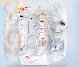
Filters come packaged as shown in Figure 1 below.
Figure 1: ST 150 Filter compatible with either machine.
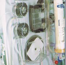
Figure 2: Filter loaded into Prismaflex in preparation for priming
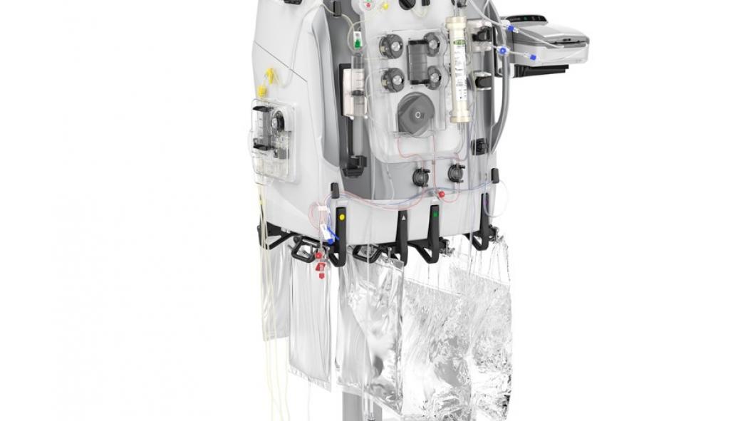
Figure 3: Tubing loaded into Prismax
ROUTING OF TUBING
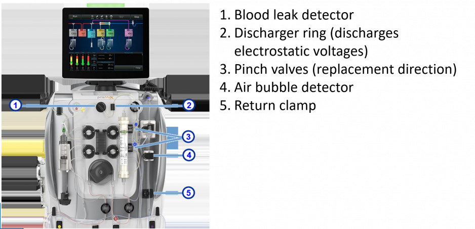
Once the filter is installed, pressure pods are connected to perform the various pressure measurements (see below). The effluent tubing is inserted into the blood leak detector which will identify any change in effluent consistency that might suggest a leak in the filter membrane (there should be no blood or protein in the effluent). The discharge ring reduces electrical interference. Two pinch valves located in the return tubing allow replacement fluid to be returned as either pre or post dilution. Returning blood must pass through an air bubble detector prior to return. Finally, a return clamp protects the patient from inadvertent air entry into the returning blood. Anytime a red high priority alarm is activated, the return clamp will close to go into the "safety mode" (Figure 3).
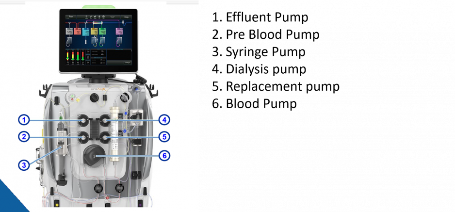
Figure 4: 5 Pumps of PrisMax
THE 5 PUMPS WITHIN THE PRISMAXTM AND PRISMAFLEXTM
BLOOD PUMP
The blood pump pulls blood from the access side of the dialysis catheter and returns the blood at the same rate of flow. Higher blood flow rates are used in CCTC to reduce clotting when no anticoagulation or heparin prescriptions are used (goal 250-300 ml/min). When citrate is used, the blood flow rate should be maintained at a consistent rate (usually ~150 ml/min) to stabilize the citrate and calcium chloride infusion.
DIALYSIS PUMP
The dialysis pump delivers dialysate fluid at the prescribed rate. Dialysate fluid enters the filter at the return side of the filter, flows into the filter cannister and around the outside of the hollow fibers of the filter, and exits into the effluent. Dialysate will be delivered AND removed from the filter at the same rate (e.g., if 1 litre of dialysate is administered, there will be 1 L of effluent collected over and above any fluid removal).
Dialysis fluid is used to promote solute removal based on the diffusion gradient. Clearance can be influenced by the concentration gradient and the rate of solute Increasing the rate that fresh dialysis fluid is administered can increase the rate of solute removal. Solute removal is referred to as "clearance".
PRE BLOOD PUMP (PBP)
The PBP delivers replacement fluid into the blood circuit immediately after the blood is pulled into the circuit at the access site. Consequently the PBP can be used to deliver anticoagulants, ensuring they enter the blood circuit as soon as possible We use the PBP for the administration of citrate.
The PBP is a "replacement pump" is also a form of hemofiltration. Hemofiltration refers to the removal of large volumes of plasma water across the dialysis filter in order to "drag" even more solutes toward the effluent side than would be lost by diffusion gradients alone. Hemofiltration is used to promote clearance. All fluid that is administered via the PBP is administered to the blood circuit "before" or "pre" filter, therefore, any fluid that is administered via the PBP circuit is a form of predilution hemofiltration. The effluent removal rate always increases automatically to match the PBP rate to maintain a neutral balance.
REPLACEMENT PUMP
The replacement pump delivers IV therapy at a prescribed rate. The replacement fluid is delivered into the blood circuit at the blood circuit either before or after the filter. The operator chooses the delivery location as "pre" or "post" dilution ot indicate the location of administration. The effluent pump will automatially increase the rate of effluent removal by the rate of replacement delivery (the replacement volume in = the effluent volume out to maintain a net neutral balance).
Predilution replacement dilutes the blood before the plasma water is removed. This may be associated with less clotting in the filter. Post dilution replacement therapy removes the plasma water at the filter before the volume is replaced. This concentrates the blood in the filter to increase the diffusion gradient and is associated with more effective clearance. Post dilution gains (increased clearance) may be negated by shorter filter life.
In practice, the difference in clearance between pre and post dilution is insignificant and does not prevent us from clearing solutes. We can clear most patients adequately without adding dialysis as long as the desired total effluent dose is achieved with hemofiltration.
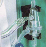
DEARATION CHAMBER
Blood leaving the filter, will pass though a heater to maintain normothermia. Any air that collects in the circuit (which can include outgasing during the heating of bicarbonate containing solutions) will pass though a dearation chamber designed to evacuate air before the blood is returned to the patient. The air fluid interface can promote clot formation in the dearatoin chamber. To prevent this, we always run a small amount of post dilution replacement fluid to minimize clot formatoin. Because the only way to administer post replacement therapy is via the replacement pump, we always set the replacement pump to deliver "post' replacement therapy. Predilution can be simultaneously delivered via the PBP.
Figure 5: Dearation Chamber
EFFLUENT PUMP
The effluent pump pulls plasma water from the patient's blood stream across the dialysis filter at a preset volume. Total effluenct volume per hour will be equal to the net fluid removal + the sum of the dialysis, preblood pump and replacement volumes.
SYRINGE PUMP
A syringe pump for the delivery of small volume anticoagulant dosing (e.g., heparin) is included in the circuit.
FLUID BALANCE
Any fluid administered on the replacement, dialysis or PBP pumps will be matched by equal effluent removal. Only fluids administered outside these circuits (e.g., IV therapy administered intravenously on infusion pumps or enteral feeding) need to be incorporated into fluid balance calculations.
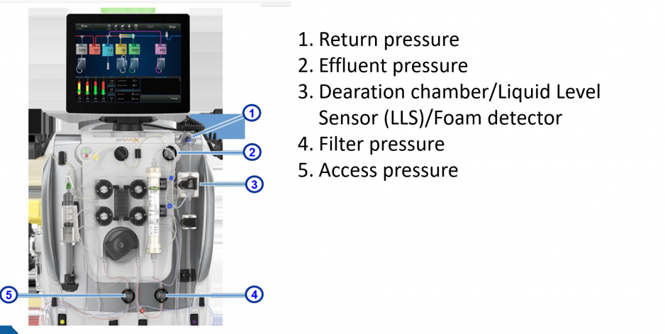
Figure 6: Pressure pods on PrisMax (same format at PrismFlex)
BLOOD FLOW AND ACCESS/RETURN PRESSURES The filter tubing is large with a low resistance to flow. The effort required to "pull" blood at the prescribed blood flow rate is influenced by the size of the tubing, the patency of the filter (less resistance required at the start of a therapy when the filter is new), the size of the catheter and the blood flow rate. The higher the blood flow, the harder the "suck" required to pull the prescribed volume.
The machine cannot tell if a catheter is truly disconnected. Instead, it measures the amount of "negativity" required to pull blood from the access port (negative pressure) and the amount of "push pressure" that is required to return the blood to the return side. The Prismaflex expect that it will take at least - 10 mmHg to pull the blood and at least + 10 mmHb of pressure to return the blood. If the blood flow rate is too low, the access pressure may not become negative enough or the return pressure may not become positive enough. Thus, an access that is more positive than - 10 mmHg or a return that is less positive than + 10 mmHg will trigger an access or return disconnect.
If an access or return disconnect alarm occurs, check the connection for integrity. If the luer lock device is intact, increase the blood flow rate until sufficient access and return pressures are generated.
FLOW RATES
The usual flow rates in CCTC are (varies with prescription):
Blood flow 250-300 ml/min
PBP 1-2 L/min
Replacement (always post) at 200-1000 ml/min
Dialysate 1-2 L/min
Patient size, clearance requirements and the use of citrate are factors that may influence the actual rates.
The PrismaflexTM / PrisMaxTM have broad flow rate capabilities for blood flows, dialysate and replacement rates. Machines can deliver up to 8 L/hr per hour of therapy (dialysate, replacement plus PBP). To achieve maximum flow rates, a larger filter with higher blood flow capacity may need to be used and the circuit primed differently than the conventional priming. Maximum flow rates are not the usual practice in CCTC.
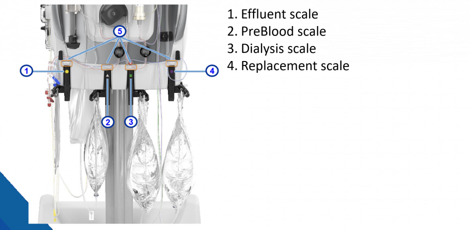
FLUID MEASUREMENTS
Both machines determine fluid volumes by changes in the bag weight. Sensitive scales determine the rate of volume change for the effluent and for the PBP, dialysis and replacement solutions. Syringe pump technology determines the anticoagulation volume delivery.
Figure 7: Prismax Scales
Machines are always set up to deliver the maximum therapy mode of CVVHDF (Continuous Venous to Venous Hemodiafiltration) with a syringe pump. If we do not want to use any of the options, we turn the flow rate for the unneeded therapy to "0" ml/hr. This maintains the option to add or change therapy at any time without needing to replace the filter.
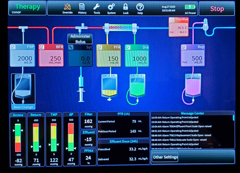
DISPLAY
The PrisMAXTM has a new touch screen display that allows visualization of the therapy as it is running. Each solution, corresponding tubing and screen display is color coded. Colores include: PBP (white), Dialysis (green), Replacement (purple) and Effluent yellow. you to visualize the therapy that is running. A real time flow path displays the therapies along an access to return continuum, displaying the treatments in the correct cicuit order. Flow rates are displayed with the pump. In Figure 8, the colors have not reproduced as they appear on the display. Note that PBP enters the circuit first, before the blood pump (denoted by the blood flow rate (BFR). The syringe pump comes after the blood pump but before the filter. Note that dialysis runs in to the distal end of the filter, and drains backwards toward the proximal end where effluent collects. Patient Fluid Removal (PFR) is the set rate of net fluid removal, and reflects the effluent removed in excess of any volume required to maintain neutral PBP, dialysis and replacement volumes. The heater is located before the dearation chamber and displays the target temperature. This is the temperature of the blood as it enters the return tubing. The replacement fluid is shown returning into the dearation chamber (post replacement). You can also see that the replacement fluid is being delivered "post" in the upper right corner of the replacment flow rate box.
To change the flows, touch the desired parameter.
On the bottom of the screen, pressures are displayed. Note that the white arrows indicate the current pressure for access, return, TMP and delta P. Alarms are automatically set to 50 above and below the current pressure. Pressures within the yellow indicate the need to assess for problems, while the red area is entering the zone for shut down.
Note the digital displays for Filter Pressure, Effluent pressure and Post Filter Hematocrit. The current and previous hour fluid removal is displayed, along with the prescribed and delivered dose of effluent (goal for delivered effluent is 20-25 ml/kg/hr).
Figure 8: Display
REFERENCES
Baxter Training Manual 1 and 2
Slides from Baxter Training package, reproduced with permission
Revised: July 2, 2013, January 30, 2015, December 14, 2020