Procedure: Setup and Use of Codman Drainage Unit for Lumbar ICP Monitoring and Drainage


Ensure that patient and health care provider safety standards are met during this procedure including:

  • Risk assessment and appropriate PPE
  • 4 Moments of Hand Hygiene
  • Procedural Safety Pause is performed
  • Two patient identification
  • Safe patient handling practices
  • Biomedical waste disposal policies
  1. System Overview
  2. Obtain Equipment
  3. Open Unit
  4. Prepare Panel
  5. Prime the Unit
  6. Position the Transducer
  7. Set Drainage Level
  8. Zero Transducer
  9. Connect to Patient
  10. Patient Monitoring
  11. Documentation

PROCEDURE FOR SETUP AND USE OF CODMANTM DRAINAGE  UNIT FOR LUMBAR CSF PRESSURE

Nurses may prime and connect the CSF drainage system in CCTC.  All CSF draining catheters (intraventricular; lumbar ICP) must be connected to the Codman External Drainage System (EDS 3TM) for safety.

Although EVD drains in CCTC are usually inserted using a microsensor technology, lumbar CSF monitoring is achieved through a fluid filled pressure monitoring circuit only. A standard transducer is used to measure Lumbar CSF pressure.

Before starting:

Review the Procedure: Insertion and Setup of Codman EDS 3TM External Ventricular Drainage Unit

Lumbar CSF pressure monitoring is performed using the same principles as fluid filled EVD pressure monitoring. The primary difference is the difference in reference level and head of bed position. Review the Procedure: Measurement of ICP Using Fluid Filled EVD Monitoring System (standard transducer)

Reason for Monitoring Lumbar ICP

During thoracic aneurysm repair, blood flow to the thoracic and lumbar spines can become compromised during aortic cross clamping. Ischemia to the cord can lead to cord edema, which can cause the lumbar ICP to rise and impede normal flow of CSF within the spinal canal. If the lumbar CSF pressure increases, drainage of CSF may reduce the risk of cord damage by reducing the pressure. Normal lumbar CSF pressure is equal to ICP if the patient is flat (< 10 mmHg).

Thoracic or lumbar spinal cord damage causes high level paraplegia. In addition to lumbar CSF pressure monitoring and drainage to maintain "lumbar ICP" target, hourly spinal cord assessment is required in the acute phase to promptly detect signs of cord impairment.  Edema can take ~48 hours to peak (following the last injury/ischemic insult). Document in the spinal section of CCTC flowsheet.

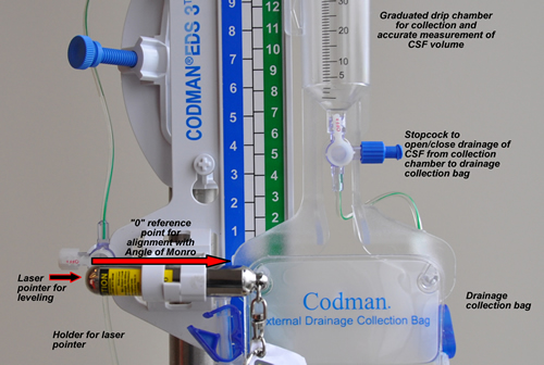
The Codman EDS 3TM is a closed system for drainage and pressure monitoring of CSF containing catheters. An antimicrobial filter located at the top of the graduated collecting chamber and bottom of the drainage collecting bag prevents backward flow of fluid or bacteria. The unit must hang upright at all times. If it is placed flat in a horizontal position, the filter at the top of the drip chamber can become wet, preventing the system from draining properly.

The panel has a "0" reference point that must be positioned at the level of the catheter (in CCTC, the lumbar spine is approximated as being level with the iliac crest in a patient lying supine). The drip chamber buretrol is then adjusted up or down until it is at a level equal to the maximum desired intracranial pressure.  Lumbar CSF pressure is normally equal to intracranial ICP. If the system is open to drainage, CSF will drain as soon as the pressure in the lumbar space exceeds the pressure determined by the height of the drip chamber above the catheter.

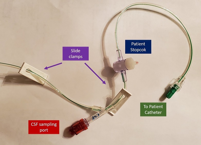
The Codman drainage unit uses 3-way stopcocks.  The stopcock can be opened in 3 directions simultaneously. The direction the prong points to represents the "off" position. This system may be utilized for continuous pressure monitoring alone, continuous drainage alone or continuous drainage and pressure monitoring. For all fluid filled pressure monitoring, the stopcock must be turned "off" to drainage and "open" to the patient catheter and pressure monitoring system when obtaining a pressure.  If pressure is measured when the drainage unit is open in all 3 directions, the pressure measured will be a reflection of the patient and drainage bag, and thus be inaccurate.

With intracranial ICP monitoring, Cerebral Perfusion Pressure is calculated each hour to ensure that there is a sufficient pressure gradient to maintain cord perfusion. When monitoring lumbar ICP, a "Cord Perfusion Pressure" can be calculated each hour using the same formula.

Cord Perfusion Pressure = MAP - Lumbar (CSF Pressure/ICP)

A low blood pressure poses a serious risk to the spinal cord. Vascular orders include a target blood pressure that is generally higher than usual baseline orders.  If neurological finding develop or ICP is elevated, strategies to increase the systemic blood pressure will usually be ordered. This is to ensure an adequate perfusion pressure is provided to the spinal cord (as well as other vessels that come off of the thoracic and abdominal aorta).  Baseline hypertension is also common among patients undergoing aneurysm surgery.


Zero
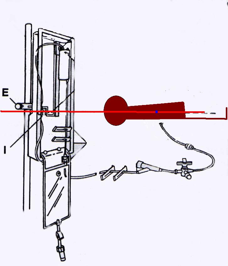
Figure 1.01: Lumbar ICP/CSF pressure is zeroed to the iliac crest.


The Drainage Unit 

The panel (left) must be positioned in an upright position, with the "0" reference point (E) at the level of the patient's catheter. In CCTC, we use the iliac crest as the lumbar ICP reference point. 

The drip chamber is ordered to a level (in cmH20) to maintain a desired lumbar ICP (normal is the same as intracranial ICP if the bed position is flat). 

New orders may be required if the drainage output is higher than the maximum orders or if the ICP is below a minimum level.

Head of Bed

If the head of bed is flat or minimally elevated, the lumbar ICP should equal the intracranial ICP. ICP in the lumbar space may become higher if there is a flow obstruction due to cord edema.

HOB is usually kept close to flat to prevent overdrainage of intracranial CSF.  Overdrainage or excessive lower of the lumbar ICP can increase the risk for intracranial bleeding.


drain
Figure 1.02: Drainage uni


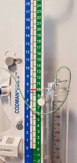
Buretrol Close-up

  • Has a roller to adjust drip chamber up and down
  • Green numerical column represents height of drainage column in cmH20, while blue column displays the equivalent mmHg (as seen on the bedside monitor).
  • Drainage tubing
  • Filter
  • Level of drainage (drip point)
  • Fluid collection
  • Arrow for alignment of drip chamber with level of desired pressure in cmH20 is the column to the right (red on panel). The corresponding pressure in mmHG is displayed to the left of the cmH20.
  • Drain level
    Figure 1.03: Adjusting the level of the drainage chamber

4-Way Stopcock 

The prong is pointing to pathways that are closed. This picture on the left displays the stopcock "open" to the patient, the drainage system and pressure monitoring.

Stopcocks and patient connections
Figure 1.04: Patient end of EDS 3 tubing


PROCEDURE

 1.

Prime the Unit

Review the Procedure: Insertion and Setup of Codman EDS 3TM External Ventricular Drainage Unit


 2.

Position the Transducer

  1. Securely tape the transducer to the side of the mounting panel with the air fluid interface (the air evacuation port of the stopcock above the transducer) at the same horizontal position as the "0" reference on the mounting panel.
  2. Connect the transducer cable to the bedside monitor.
  3. Using the laser level, ensure that the "0" reference on the panel is level with the iliac crest if patient is supine.


Both the transducer and the mounting panel stopcock must be level with the lumbar space.

By securing both stopcocks at the same point, the transducer and mounting panel can be simultaneously referenced by adjustment of the mounting panel.

3.

Set the Drainage Level

  1. Obtain an order for the level of the drainage chamber. 
  2. Orders should include a maximum CSF volume to drain and both a MINIMUM and maximum lumbar ICP. The minimum is used to prevent ventricular dehydration which may increase for bleeding.
  3. Loosen the buretrol adjustment screw and move the drip chamber until the small arrow is aligned with the desired height.  
  4. Tighten the screw to secure the buretrol position.

If the "0" reference is level with the patient's catheter, a drainage level of 10 cmH20 above the lumbar space provides automatic "venting" of CSF if the pressure rises above 10 cmH20. 

If the "0" reference and the drip chamber are both positioned level with the catheter, drainage would occur the moment the lumbar CSF pressure > 0.  Normal lumbar CSF pressure is < 10 mmHg.  This could lead to over drainage and potential for cerebral bleeding.

Weaning of the drainage system can be done by raising the level of the drainage unit (the ICP would have to be higher before drainage would occur). Intermittent drainage may also be initiated, where pressure is monitored and drainage only opened if the pressure exceeds a specific level.

Both the patient and mounting panel stopcocks must be open between the patient's catheter and the drainage chamber for drainage to occur. When the system is left continuously open to drain and the drainage chamber is positioned to initiate drainage at a set level, pressure is maintained at a more consistent level. 

Note that the bedside monitor measures pressure in mmHg; 10 cmH20 is the same as 7.4 mmHg.  Thus, a properly positioned unit with the drip chamber at 10 cmH20 will drain if:

  • the stopcocks are open between the patient's catheter and the drip chamber
  • the pressure in the lumbar space exceeds 10 cmH20 (or exceeds 7.4 mmHg on the bedside monitor).
  • the catheter/circuit is patent (e.g. free of clot or debris)
  • there is fluid in the lumbar space (if the pressure is high due to cord edema, there may not be any CSF to drain)

If the circuit fails to drain despite a pressure on the monitor that is > than the level of the drainage chamber, patency can be assessed by lowering the entire drainage unit to below the head.

Notify CCTC resident AND Vascular Surgery if the unit fails to drain in the presence of an elevated pressure despite troubleshooting efforts

A typical order is "10 cmH20" above the lumbar space. The right hand (green) column of numbers of the Codman drainage unit is in cmH20.  The column to the left (blue) displays the equivalent pressure in mmHg (7.4 mmHg - 10 cmH20).). 

In the example of "10 cmH20", the system is correctly placed if the "0" reference point is level with the patient's iliac crest and the small arrow is aligned at the 10 cmH20 marking, drainage would be expected if the bedside monitor identifies a pressure > 8 mmHg.

If the lumbar drain is in the open position, raising the head of bed can increases the pressure gradient between head and lumbar spine and can lead to over-drainage. Continuous drainage is safest with the HOB close to flat.

Excessive fluid removal or reduction in the intracranial pressure can increase the risk for intracranial bleeding.

Turn stopcock off temporarily any time the drain needs to be moved to below the reference level.

A minimum ICP should be identified to prevent intracranial dehydration which may increase risk for bleeding.

Turn drain off to drainage if output exceeds ordered maximum (usually 10-20 ml/hr). If pressure is low, an order to raise the drain level or to switch to intermittent drainage may be indicated.

7.

Zero the Transducer

  1. Select "ICP" as the monitor label.
  2. Open the transducer stopcock to air (taped to the mounting panel).
  3. Press "zero" on the bedside monitor.
  4. If the ICP is > 20, the scale will need to be increased.  

8.

Connect to Patient

  1. Perform hand hygiene and don non-sterile gloves.
  2. Connect the lumbar catheter to the drainage unit.
9.

Patient Monitoring

Monitor lumbar ICP hourly.  Turn stopcock off to drainage for one minute each hour to obtain an accurate measurement.

Patient should have an arterial line for continuous blood pressure monitoring and calculation of Spinal Cord Perfusion Pressure hourly.

Monitor spinal cord function hourly for the initial 12 hours and if lumbar ICP is elevated.  Frequency may be decreased to Q2H per vascular surgery recommendations. Edema risk remains for at least 48-72 hours.

Monitor for acute change in bowel or bladder function (e.g., sudden diarrhea).  This may indicate acute spinal cord ischemia.

Notify CCTC physician AND Vascular Surgery immediately:

  • If blood pressure falls below target
  • If lumbar ICP remains above target despite drainage
  • If Spinal Cord Perfusion Pressure (MAP - lumbar ICP) falls below ordered target or previous trends
  • For any change in spinal or neurological assessment or changes in bowel function (indwelling Foley impedes bladder pressure monitoring.


10.

 Documentation

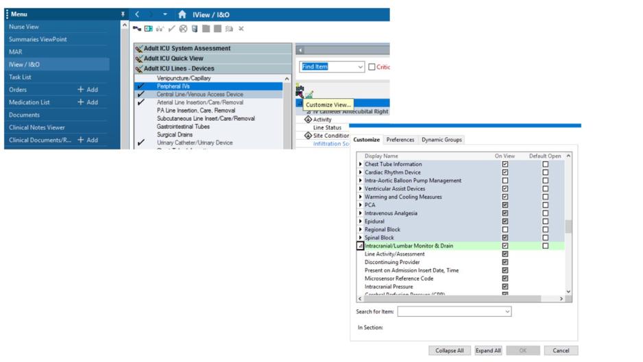
In IView, select the Adult ICU Lines - Devices Navigation Band. If you do not have Intracranial/Lumbar Monitor and Drain as an option, select it from custom view. Select the Intracranial/Lumbar drain type and create a Dynamic Group. Record Pressures and Hourly Output.

Creating Dynamic Group ICP
Create a Dynamic Group for documentation of ICP or CSF drainage.


References:

ACCF/AHA/AATS/ACR/ASA/SCA/SCAI/SIR/STS/SVM (2012) Guidelines for the Diagnosis and Management of Patients With Thoracic Aortic Disease: http://dx.doi.org.proxy1.lib.uwo.ca/10.1161/CIR.0b013e3181d4739e

Khan. (2012) Cerebrospinal fluid drainage for thoracic and thoracoabdominal aortic aneurysm surgery. Cochrane Vascular Group.

Ishikawa (2012). Acute subdural hematoma following thoracoabdominal aortic repair in a patient with Marfan syndrome: a rare complication of cerebrospinal fluid drainage.Ann Thorac Cardiovasc Surg. 18(5):488-90. Epub 2012 Mar 24.

Ullery. (2011). Risk factors, outcomes, and clinical manifestations of spinal cord ischemia following thoracic endovascular aortic repair. Journal of Vascular Surgery, September.

Fedorow (2010). Lumbar Cerebrospinal Fluid Drainage for Thoracoabdominal Aortic Surgery: Rationale and Practical Considerations for Management. Anesthesia & Analgesia. 111(1), 

Developed by:
Brenda Morgan 
CNS, CCTC
Initial Procedure: November 1988

Last Update: February 1, 2020 (BM); Reviewed: January 31, 2024