Published: 2023-09-06 Author: Mike Apostol
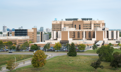
It can be easy to take for granted how we keep our hospitals cool throughout the hot summer days. But a lot of infrastructure, technology, and effort goes into cooling our buildings. For those in Facilities Management responsible for this system, keeping it performing optimally is top of mind as temperatures soar.
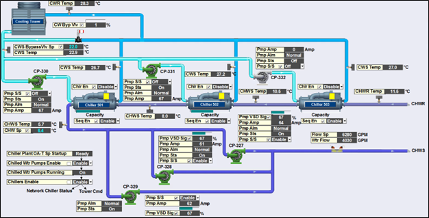
Just take a look at the screenshot above of our Honeywell Building Management software for the chilled water system to see the complexity of what our Building Engineers need to monitor; there are chillers, pumps, cooling towers, piping, and all the data points monitored with each of them. If you're interested in understanding how all this works in more detail, check out the How Cooling Systems Work section at the bottom of the article.
University Hospital's Control Valve Upgrade
In recent years, University Hospital cooling system has sometimes struggled to keep the hospital cool on the hottest days. So, we're revitalizing the cooling infrastructure to address the old control valves that leak, old and poor-performing cooling coils, increased equipment loads, and ensure our system reliability during extended periods of severe hot weather.
One of the first significant upgrades we completed this past winter was to improve the control valves that control how chilled water is moved around the cooling loop. The neat thing about our building management software is that we can make sure that we're seeing an improvement in our system performance and then with all that data we can calculate our energy savings!
Control Valve Energy Savings
One significant improvement that the control valves help with is reducing the amount of chilled water that needs to be pumped around, as the various "legs" of the cooling loop are better matched for chilled water demand and the amount of flow sent to them. So, we expected to see reduced flow and consequently reduced electricity needed to pump all that water in the chilled water loop.
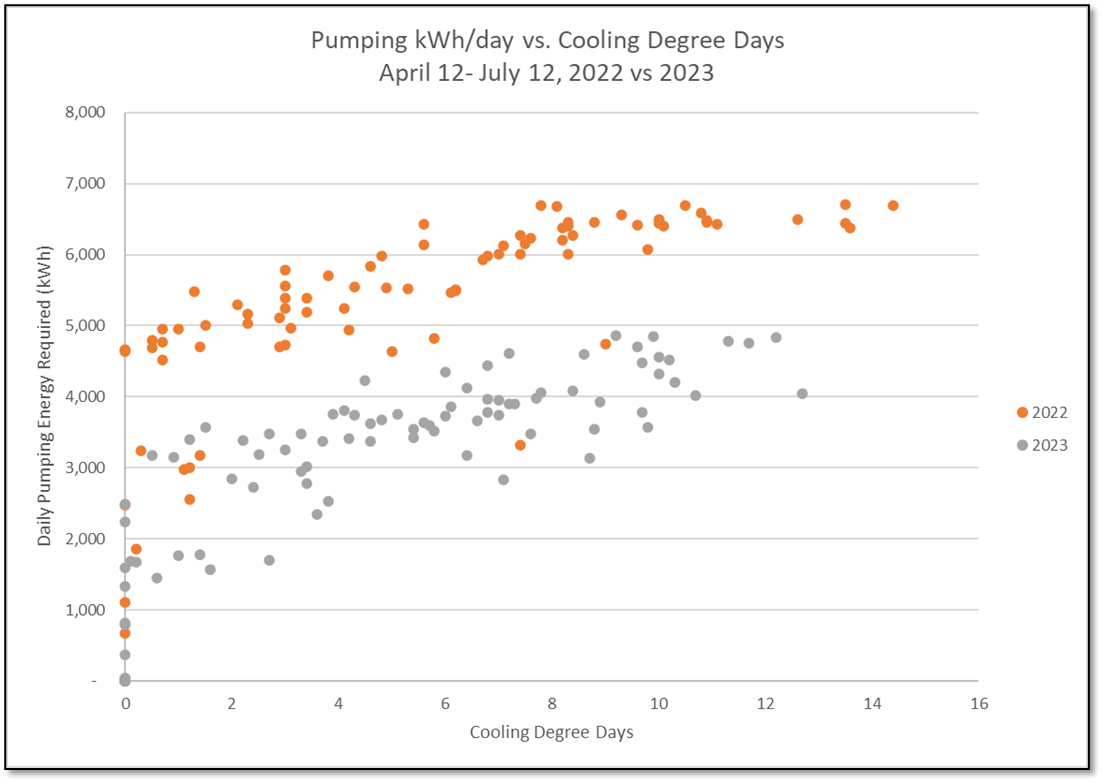
When we looked at the data comparing the first half of last year's cooling period from April to July in 2022 and then this year's in 2023 after the retrofit, the typical flow of the chilled water loop dropped an astounding 50 per cent, or an average of 4,800 gallons per minute (GPM) down to 2,300 GPM.
Because of this flow reduction, the pumps that move all this chilled water around use less electricity, saving us around 400,000 kWh per year and $50,000 per year in pumping electricity costs. That's the equivalent of approximately 40 houses worth of annual electricity usage! The graph in the image shows this decrease in pumping energy required per day based on how hot the day is, which we characterize through cooling degree days.
These are just the savings from our main chilled water pumps, as we also have a few other smaller booster pumps in other parts of the hospital that also show improvements.
With the upgrades to the new control valves and replaced bypass valves, we've also seen the temperature difference between the supply and return chilled water improve from around 4°C to 6°C, improving our chillers' operational efficiency.
Although this is a significant improvement, we are working on further improvements with the upcoming chiller infrastructure project.
Conclusion
Our Facility Management team of Maintenance, Repair and Operations (MRO) staff, contractors, project team and building engineers are doing a great job ensuring the temperature is just right for the comfort of our patients and staff. The latest control valve upgrade to the chilled water system has dramatically improved their ability to maintain a cool and comfortable environment for everyone at University Hospital.
How Cooling Systems Work: The Basics
The Cooling System at University Hospital (UH) is comprised of large chillers, pumps, valves, a chilled water loop, cooling coils, and a cooling tower. This diagram below shows the connections between all the components and all the areas our Building Engineers need to key their eyes on.
You can see the complexity of what our Building Engineers need to monitor in our Honeywell Building Management software for the chilled water system in the screenshot above; there are chillers, pumps, cooling towers, piping, and all the data points monitored with each of them.
What are Chilled Water Systems?
When you have large buildings like our hospital, we keep them cool and dehumidify the air with a chilled water cooling loop system. Its essential components include a chiller and cooling towers (which cool the water), pumps (to circulate the water), and a cooling coil (where the cooled water absorbs heat).
Here are the basics of a chilled water system loop:
- Chiller operation: The water enters the chiller's evaporator from the system loop, starting a refrigeration cycle to cool this water and remove heat from it with the help of cooling towers. Afterward, the chilled water circulates back into the system.
- Circulation: A pump pushes the chilled water from the chiller into the chilled water loop. The water flows through the pipework to cooling coils within air handlers throughout the building.
- Heat exchange: At each cooling coil, the chilled water absorbs heat from the building's air, which a fan blows across the coil. The water becomes warmer as it collects this unwanted heat.
- Return to chiller: After absorbing heat, the now warmer water returns to the chiller, where the heat is once again removed, cooling the water back down. This cooled water is then re-circulated through the system. This process continues in a closed loop for as long as cooling is needed.
Control Valves
Control valves are an essential component in this system because they control the flow rate of the chilled water to the cooling coils based on the cooling demand of the building. They automatically open or close in response to signals from a temperature sensor or a building management system. This allows the system to provide the right amount of cooling to different building parts at different times, improving efficiency and comfort.
Without these control valves, the system would be unable to respond to changes in cooling demand. This could lead to overcooling or undercooling of different areas, and the chiller would run inefficiently, wasting energy. Control valves thus ensure the system's efficiency and the comfort of the building's occupants.