Breath sounds are assessed at the start of each shift and PRN. Respiratory rate, rhythm, effort and synchrony is monitored continuously for all ventilated patients.
RNs in CCTC assess the patients rate, tidal volume, minute volume, airway pressures and ventilator settings Q1H and PRN, and document findings in the eHR Q1H. RNs in CCTC provide continuous respiratory monitoring and report significant findings to the Respiratory Therapist and the provider.
2.
Monitor SpO2
All CCTC patients have continuous SpO2 monitoring, unless otherwise ordered. When digits are used for monitoring, monitoring sites are rotated and the skin integrity assessed Q2H.
SpO2 may be inaccurate in the presence of nail polish, carbon monoxide (e.g., smoke inhalation) or impaired peripheral perfusion. Blood gases provide more accurate assessment of oxygenation in these situations.
SpO2 alarms are on at all times. If alarms are disabled, the reason is documented in the AI record.
The RN is responsible for continuous monitoring and for communicating relevant findings to the appropriate member of the health care team. The respiratory therapist is responsible for the set-up and adjustment of the ventilator. RNs may increase the FiO2 temporarily for desaturations using the emergency 100% option on the ventilator. For patients with raised ICP, nurses may increase the FiO2 and give a few preemptive breaths prior to suctioning to prevent suctioning induced hypercarbia or hypoxemia.
3.
Communicate Findings
Ongoing communication between the RN and RRT responsible for the care of a patient is required. Planned changes for sedation, weaning and overall goals of care are discussed in advance and communicated upon completion.
Many factors influence a patient's ventilation requirements including hemodynamic stability, acute brain injury, procedural or operating room plans and level of sedation. Interventions must be made with full knowledge of the treatment plan and of the patient's condition. RNs in CCTC and RRTs must work as a team to ensure optimal ventilatory support.
4.
Monitor Blood Gases
All patients require daily blood gas evaluation unless otherwise ordered. Frequency reductions are indicated for stable, long-stay patients.
Blood gases are repeated within one hour of a ventilator change for acute admissions or unstable patients and to evaluate respiratory status following spontaneous breathing trials.
If changes are made to the FiO2 or PEEP to correct a low PaO2, gases do not need to be repeated if the SpO2 demonstrates an appropriate response. SpO2 may not be reliable in the presence of carbon monoxide or poor peripheral circulation.
When patients are switched from full ventilation to PS mode, blood gas evaluation is not required if the patient remains comfortable, RR is WNL, and the minute volume remains unchanged. Repeat gases If signs of respiratory distress develops.
PRN blood gases are repeated for evidence of respiratory distress, to evaluate or monitor acid-base disturbances (e.g., increased or low bicarbonate on electrolyte panel, elevated lactate, renal or hepatic failure, DKA), to assess hemodynamic instability or identify causes for new arrhythmias. Documentation in the AI record.
When obtaining a blood sample for analysis on the Point of Care technology, all samples must have a patient identification label on the syringe before being transported to the bedside.
When entering the patient data in to the Point of Care Technology, ensure that you select the correct sample (arterial or venous). include the patient's temperature, FiO2, PEEP and minute volume into the Point of Care program and ensure that the sample is rotated along 2 planes (See Procedure for Blood Gas Sampling).
5.
Provide Emergency Equipment
Each bedside will have a manual resuscitation bag connected to oxygen and a ventilation mask. If PEEP > 5, a PEEP valve is added to the bag-valve-mask resuscitation bag.
An intubation box is kept in each Bay.
The emergency airway cart (kept in the Respiratory Supply Room by Bay 3) should be add the bedside prior to intubation/tube exchanges.
6..
Maintain Positioning
All intubated patients will be nursed with the head of bed elevated > 30 degrees unless contraindicated. The bed position will be documented in degrees in the eHR. If the HOB is not elevated > 30 degrees, the rationale is documented in the Assess/Reasses.
7.
Suction as Required
Appropriate PPE is required when suctioning please refer to:
Suctioning is done prn. Patients on neuromuscular blocking agents or who are paralyzed are suctioned twice per shift and prn with an assisted cough technique. A closed-system in-line technique is used.
Suctioning catheters are rinsed with sterile saline following each suctioning episode.
Suctioning efforts are documented in the graphic record. Findings not WNL are documented in AI record.
Suctioning is only done when indicated to reduce unnecessary airway trauma and patient discomfort. Patients with paralyzed diaphragms are more difficult to assess and often have secretions not detected audibly due to impaired cough. Assisted cough technique facilitates clearance in the absence of a cough.
8.
Change Chest Tube Dressings
Chest tube dressings are changed q 2 days and prn. Ensure appropriate PPE is utilized when performing chest tube dressings (hand hygiene and non-sterile gloves).
Dressing changes are documented in the graphic record. Findings not WNL are documented in AI record.
9.
Assess Chest Drainage Systems
At the start of each shift assess each chest tube for the following and document in the EHR:
Presence/adequacy of underwater seal (assess with suction off; should always be at 2 cm) Figure 1.01
Presence of fluctuation in the water seal (assessed with suction off) Figure 1.02
Presence of an air leak; rate on a scale of 0-7/7 (or 1-5/5 for units with only 5 columns) shown in Figure 1.03.
Adequacy of suction/suction level as per order Figure 1.04
Presence of rescue bottle of water (see below)
Ensure that a bottle of water is availabe for each tube (see #10)
When draining blood or pleural fluid, monitor closely for hypotension. If a rapid or large output drains immediately, review with provider the need to clamp/gradually remove fluid (especially pleural fluid). Fluid or blood replacement may be required. Fluid replacement should be given with caution in pleural effusion as fluid overload may be the underlying cause for the effusion.
For hemothorax, clamping can induce a tension hemothorax; rapid blood loss or blood loss that does not decline after initial drainage suggests on going bleeding and may be a surgical emergency.
Immediately following insertion, the chest tube should fluctuate and will have an air leak (if inserted for a pneumothorax). Notify provider promptly if there is no initial fluctuation or air leak, or if there is unanticipated hemothorax as this may indicate malplacement of the tube.
Reassess the need for Chest Xray and ongoing chest tube placement during rounds each day. Resolution of a previous air leak and loss of previous fluctuations suggest that the pneumothorax is resolved.
A tube placed for hemothorax should have a steady but gradual decline in the volume of hourly blood. There may be an initial large volume, but the hourly amount should gradually decrease each hour. Following turning, there may be a sudden loss of blood or pleural fluid if a tube is draining fluid, as a pocket of fluid is accessed by the drainage tube. If a chest tube that is draining blood abruptly stops draining, clotting of the tube should be considered. A clotted tube will behalf like a clamped tube and may cause a tension hemothorax.
Maintenance of the underwater seal is the most important component of a chest drainage system.
The underwater seal chamber is divided into 7 (or 5) vertical columns to provide a semi-quantitative assessment of the amount of leak. Identify the highest number where air bubbles are detected to determine the severity of the leak and document out of 7 (or 5). For example, a leak of 1/7 (bubbles only in the first column) is very small. A leak of 4-5/7 or higher is a significant leak.
The presence of a leak indicates that air is being drawn through the system. It does not differentiate air from a pneumothorax versus system leak.
Fluctuation indicates that the chest tube is likely in the pleural space and patent, and able to detect the changing pressures during breathing. When a tube is not fluctuating, it suggests that the tube is either outside the pleural space, the tube is occluded, or the lung has rexpanded and the pneumothorax is resolved.
When a pneumothorax resolves, reexpansion of the lung will compress the drainage holes and prevent the detection of the pleural space pressure changes.
When the air leak is gone and the underwater seal stops fluctuating, patient should be reassessed for readiness to remove chest tube.
Clamping of chest tubes should be avoided (except for momentarily while changing chest drainage units). This is particularly important among patients who have an air leak or active bleeding, as clamping can precipitate a tension hemo/pneumothorax and/or increase the risk for clotting of the tube.
If a chest tube becomes disconnected, immediately submerge the chest tube into a bottle of water with the connection port located at least 2 cm below the meniscus (or reconnect quickly). A level of 2-5 cm is likely safe in most patients. If reconnected, the connections should be cleansed and chest drainage unit changed as soon as able.
Always ensure there is water in the underwater seal. This is the most important step before connecting a chest drainage unit. This is good practice even when using a unit with a waterless underwater seal valve (that does not require water to create a one-way valve). Waterless or water filled one-way valves still require the water to be added for diagnostic purposes; by always making this standard practice errors do not happen when product substitutions occur.
Maintain a bottle of sterile water at the bedside at all times for each chest tube. Ensure that a bottle of water accompanies the patient during any transit.
Small Bottles of Water
Small 59 ml bottles (Figure 1.05) are available for this use from the cart in Bay 3 with the chest drainage supplies. Keep one for each tube at the bedside. It can be taped to the chest drainage unit. Check at the start of each shift to ensure a bottle of water is available.
Small bottles can be used to create a quick underwater seal. Always ensure that the tube is a MINIMUM of 2 cm below the level of the water meniscus (Figure 1.06). Insert the chest tube halfway into the mini bottle. This will provide a temporary underwater seal of ~4 cm H220 (Figure 1.07). Insertion halfway is easier to maintain than a more superficial level and should still enable air evacuation if the patient has a significant leak.
Tape or hold the tube into position so that it doesn't flip out of the water. If the tube is taped into position, ensure that there is adequate room for venting of air around the bottle neck.
This temporary measure will prevent air from reentering the chest. Be aware that the deeper the tube is inserted, the more difficult it will be for air to be evacuate air. Deep insertion will function the same as clamping the tube. Monitor closely for respiratory distress, particularly if the patient had a previous air leak.
Figure 1.05: Small bottles for emergency underwater seal
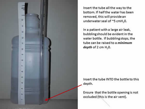
Large Bottles of Water
It is harder to visualize the depth of the tube within the larger bottles, therefore adjusting the water level and inserting the tube to the bottom of the bottle provides easier depth assessment. Dump approximately half of the water out of the bottle (to 250 ml level) (Figure 1.08). This will provide a 5 cm water level if the chest tube is inserted all the way to the bottom (Figure 1.09).
If the level of water is less than 2 cm of water, the "air seal" is inadequate and can allow air to enter the pleural space, creating a larger pneumothorax. If the level of water is too high (greater than 2 cm of water), it becomes harder for air to be evacuated. This can mimic clamping.
When a chest tube becomes disconnected, air can quickly be drawn into the pleural space. Clamping will prevent evacuation of the air and can create the environment for a tension pneumothorax.
Any sudden disconnection, particularly among a patient with an existing air leak or receiving mechanical ventilation is at the greatest risk of tension pneumothorax during clamping.
The volume of water, presence of fluctuations and degree of air leak is best assessed with the suction temporarily stopped.
Risk of Deep Submersion
In the event that a chest tube becomes disconnected in a patient with a signficant air leak or pneumothorax, monitor the depth of the chest tube closely until a new unit can be set-up. An air leak should continue to be visible in the water bottle; if it is not, withdraw the tube until a leak resumes (ensuring a minimum depth of 2 cm H20 is maintained at all times).
MRI Compatibility
The small bottles have a metal cap. For patients traveling to MRI who have chest tubes, take a standard 500 ml regular bottle of sterile water.
Changing Chest Drainage Units
Temporarily clamp the chest tube (with 2 kelly clamps) when changing the chest drainage collection unit. In patients with a persistent air leak this should be done as quickly as possible.
Figure 1.06: Depth of water in 59 ml bottle of water
Figure 1.07: Depth of water at 4 inches 59 ml bottle of water
Figure 1.08: 5 inches of water in 500 ml bottle of water after dumping half the volume.
Figure 1.09: Submersion into half filled 500 ml bottle provides a water seal of 5 cmH20
11.
Document Chest Tube
Document respiratory assessment at the start of each shift and Q4H PRN.
Create a Chest Tube Dynamic Group in the Adult ICU System Assessment under Chest Tube Information. Assess the underwater seal volume, suction setting, presence of bubbling, fluctuation and air leak (graded by the number of the columns where bubbling is visible Figure 1.03). Assess Q15 minutes X 4 following insertion, Q1H during initial 12 hours, then Q1-12 hourly depending upon output and persistence of leak.
Enter the true hourly output (Figure 1.10) in the Chest Tube Grouper. This will be pulled to the fluid balance record.
For persistent or maximal leak, double check all connections and notify provider. A persistent or maximal leak could indicate a surgical emergency such as esophageal or airway rupture. Notify provider if persistent bubbling with a reduction in exhaled tidal volumes - this may indicate the presence of a bronchopleural fistula.
Keep the chest drainage unit in an upright position to avoid transfer of drainage between columns.
Figure 1.10: Single drainage collecting unit with 4 graduated fluid collection columns.
When drainage has filled incompletely as shown above, the unit can be tipped to move fluid from one chamber to another to align the volume correctly.
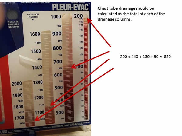
Chest drainage fluid drains into vertical cannisters. The right hand cannister fills first, then spills over to fill the next cannister toward the left. If the drainage unit is maintained in a perfectly upright position, the graduated markings will accurately reflect the true output.
Because the drainage unit will invariably be tilted, the columns rarely fill to the top before spillage toward the left hand cannister occurs. For this reason, the sum of each column must be added to measure true output.
12.
Document Respiratory
Document respiratory assessment in the Adult ICU System Assessment Band under Vital Signs, Invasive or Non-Invasive Ventilation and Respiratory Bands.
Last Update:
February 2, 2020; Revised February 8, 2023
Brenda Morgan, CNS, CCTC